Understanding the Singer One Manual
The Singer One manual details setup‚ threading‚ buttonholes‚ maintenance‚ and troubleshooting. It highlights the SwiftSmart Threading System‚ built‑in needle threader‚ and dual‑width bartack buttonhole foot. Follow step‑by‑step instructions for optimal use; Enjoy it.
Key Model Overview and Specifications
The Singer One is a compact‚ user‑friendly machine designed for home sewing enthusiasts. It features a 12‑speed motor that delivers up to 1‚200 stitches per minute‚ making quick projects effortless. The machine accepts standard 10‑point needles (size 75/10) and supports a wide range of thread types‚ from cotton to polyester blends. Its 8‑color stitch palette includes straight‚ zig‑zag‚ decorative‚ and buttonhole patterns‚ all adjustable via a simple dial.
- Dimensions: 16.5” x 11.2” x 7.8” (L x W x H)
- Weight: 12.4 lbs (5.6 kg)
- Power: 120V‚ 60Hz‚ 1.2 kW
- Thread Capacity: 3–4 spools (up to 200 yards each)
- Built‑in needle threader and automatic bobbin winding
- Optional accessories: buttonhole foot‚ walking foot‚ quilting foot
- Warranty: 1 year limited‚ parts and labor
With its lightweight construction and intuitive controls‚ the Singer One is ideal for beginners and seasoned sewers alike‚ offering reliable performance without sacrificing portability.
The manual also covers safety precautions‚ recommended maintenance schedules‚ and troubleshooting tips for common issues such as thread breakage or motor overheating. It provides clear diagrams and step illustrations to help users resolve problems fast for all skilllevels.
Enjoy sewing!.

Initial Setup and Installation
Unbox the Singer One‚ set it on a flat surface‚ plug in the power cord‚ and insert a 10‑point needle. Load the bobbins‚ thread using the built‑in threader‚ and adjust the speed dial. Test a few stitches before starting now.
Step‑by‑Step Assembly Instructions
Place the Singer One on a stable‚ level surface. 2. Attach the power cord to the machine and plug into a grounded outlet. 3. Insert a 10‑point needle into the needle clamp‚ tighten securely. 4. Load the main thread spool onto the spool holder‚ pull thread through the tension disc‚ and guide it to the needle. 5. Use the built‑in needle threader to thread the needle: pull the thread through the eye‚ then pull the tail back through the needle. 6. Insert a bobbin into the bobbin case‚ ensuring it sits flush against the bobbin plate. 7. Wind the bobbin with the supplied spool holder‚ keeping the thread taut. 8. Align the bobbin with the needle plate‚ then close the bobbin cover. 9. Adjust the stitch length dial to the desired setting. 10. Test a short run on a scrap piece of fabric‚ checking for even stitches and proper tension. 11. If stitches are uneven‚ adjust the tension dial or replace the needle. 12. Secure the machine’s foot by placing the desired presser foot onto the foot plate and tightening the foot clamp. 13. Finally‚ perform a quick safety check: ensure all guards are in place‚ the machine is unplugged during adjustments‚ and the area is free of loose fabric. Once satisfied‚ the Singer One is ready for use. Remember to keep the machine clean‚ avoid fabric debris‚ and consult the manual for advanced settings to maximize performance. Follow the safety guidelines‚ and enjoy a smooth‚ efficient sewing experience with your new Singer One. Stay creative! —S Keep stitching

Threading and Needle Setup
Use the Singer One’s SwiftSmart Threading System: place main thread on spool‚ pull through tension disc‚ thread needle with built‑in threader. Insert a 10‑point needle‚ tighten‚ wind bobbin‚ and test a short run for stitches now
SwiftSmart Threading System with Built‑in Needle Threader
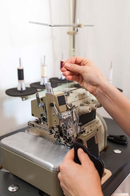
The Singer One’s SwiftSmart Threading System is engineered to reduce the time and frustration traditionally associated with threading a sewing machine. By integrating a built‑in needle threader‚ the system automatically guides the thread through the needle eye‚ eliminating the need for manual threading or the use of a separate needle threader tool. The process begins by attaching the main thread to the machine’s spool holder. The thread is then pulled through the tension disc‚ ensuring consistent tension before it reaches the needle. As the thread passes through the built‑in needle threader‚ a small‚ precisely‑cut slot directs the thread into the needle eye. This slot is calibrated to accommodate a range of needle sizes‚ from 10‑point to 12‑point‚ ensuring compatibility with most standard Singer One needles. Once the thread is threaded‚ the user can wind the bobbin by placing it into the bobbin case‚ aligning the bobbin thread with the machine’s bobbin thread guide‚ and winding the bobbin with the machine’s winding lever. After winding‚ the machine automatically feeds the bobbin thread into the needle‚ creating a balanced stitch. The SwiftSmart system also includes a quick‑release lever that allows the user to disengage the needle threader for maintenance or to switch to a different needle. This lever can be activated by a simple push‚ releasing the threader’s latch and allowing the user to manually thread a new needle if desired. The entire threading sequence is designed to be completed in under a minute‚ significantly speeding up the setup process for both beginners and experienced users. For optimal results‚ always use fresh‚ high‑quality thread and keep the needle clean; regular maintenance will keep the threading system smoothly. Its design keeps the path clear‚ reducing jams!

Buttonhole Construction Features
The Singer One offers dual‑width bartack buttonholes‚ automatically measuring button size to calculate the perfect hole. The buttonhole foot adjusts to the selected width‚ ensuring precise‚ clean edges for shirts‚ blouses‚ and more. Perfectly aligned for all now!
Using the Buttonhole Foot and Bartack Width Settings
To create a clean buttonhole on the Singer One‚ attach the buttonhole foot to the foot holder and align it so the center of the opening sits over the needle. Turn the width dial on the foot to choose the bartack width: “N” for narrow and “W” for wide. Press the buttonhole button on the control panel to activate the mode; the machine will set stitch length and depth automatically. Pull the fabric through the foot and the machine will stitch a series of short‚ tight stitches forming the bartack. After the first row‚ the machine reverses and stitches the second row‚ producing a symmetrical buttonhole. If the fabric is slippery‚ use a stabilizer or a fabric weight to keep it steady. Once the buttonhole is complete‚ remove the foot and inspect the seam for evenness. Adjust the width dial slightly if the bartack feels too tight or too loose‚ and repeat until the desired result is achieved. Keep the foot clean to avoid debris that could interfere with the stitching‚ and use the built‑in needle threader to ensure the thread is fully seated for consistent quality. Before starting‚ verify that the buttonhole foot is seated firmly on the holder to prevent slippage during stitching. For delicate fabrics‚ consider lowering the stitch length to reduce puckering. This ensures a neat‚ professional finish for results.
Maintenance and Care Guidelines
Keep the Singer One clean by wiping the exterior after each use. Remove feed dogs‚ clean with a soft brush‚ and oil moving parts. Check needle tension and replace worn belts. Store in a dry place. Regular cleaning prevents jams‚ extends machine life‚ stitches smooth!
Cleaning‚ Lubricating‚ and Parts Replacement
After each use‚ wipe the Singer One’s exterior with a damp cloth and remove feed dogs to brush away lint. Use a soft brush or compressed air to clear the feed mechanism and bobbin area. Avoid excess moisture that can seep into the motor.

Lubricate the drive belt‚ needle bar pivot‚ and feed dog rollers with a few drops of sewing‑machine oil. Only use oil specified by Singer to prevent dust buildup. Over‑oil can clog the needle path. Keep it dry and.!!!
Replace worn parts according to the schedule. Inspect the needle for bends or dullness; change it every 50–100 hours or when stitches break. Check the drive belt for cracks; replace if damaged. Clean or replace feed dogs if they no longer move evenly. Keep spare needles‚ bobbins‚ and a replacement belt handy. Also‚ replace the feed dog assembly every 12 months or if the feed dogs show signs of wear. Keep a spare set of feed dogs in your kit.
For deeper maintenance‚ consult the manual for disassembly. Clean the bobbin case‚ replace the feed dog assembly‚ and ensure tension discs are free of debris. After reassembly‚ run a test stitch to verify smooth operation. Perform a few test stitches to ensure the tension is correct and the machine runs smoothly. Following these steps extends the machine’s lifespan and guarantees consistent stitch quality.

Troubleshooting Common Issues
Check threading: ensure correct needle and proper tension. If spool jams‚ verify pin placement and wheel alignment. Motor issues may stem from worn brushes; replace them and clean contacts. Test with a fresh power source. If problems persist‚ consult manual help.

Diagnosing and Fixing Threading‚ Spool‚ and Motor Problems
When the Singer One stalls‚ start with the SwiftSmart Threading System. Remove the top cover‚ lift the needle‚ and check for a clean path. If the needle is bent or the thread is tangled‚ replace the needle and re‑thread using the built‑in needle threader. For spool issues‚ ensure the spool pin is seated in the correct slot and that the spool wheel is free of debris. A jammed spool wheel often causes uneven tension; clean it with a soft brush and re‑apply a light lubricant. Motor problems usually surface as a clicking noise or a complete stop. Inspect the motor brushes for wear; if they are less than 1 mm thick‚ replace them with new ones. Verify the power cord and plug for damage; a frayed cord can interrupt power delivery. If the machine still does not run‚ test the motor with a multimeter to confirm voltage continuity. A faulty motor relay or capacitor may need replacement. After each repair‚ reset the machine by turning the power off‚ waiting 30 seconds‚ and restarting. Always refer to the safety instructions in the manual before disassembling any component. For persistent issues‚ contact an authorized Singer repair center for professional service. Remember that maintenance‚ such as cleaning the feed dogs and checking the tension settings‚ can prevent many of these issues and extend the machine’s lifespan.!
Downloading and Accessing the Manual
Find the official Singer One PDF on the manufacturer’s site or trusted forums. Click the download link‚ save the file‚ and open with any PDF viewer. For mobile‚ use the Singer app for instant access and support today.
PDF Guides and Online Resources for Singer One
Access the Singer One manual in PDF format from Singer’s support portal. Navigate to the “Downloads” section‚ locate the model “One” under the sewing machines category‚ and click the PDF icon to begin the download. The file is typically named “Singer_One_Manual.pdf” and is 1.2 MB in size; For users who prefer a mobile version‚ the same PDF can be opened in any standard PDF viewer on Android or iOS devices. If the official site is temporarily unavailable‚ trusted community forums such as the Singer One Owners Forum and the Sewing Machine Forum host mirrored copies of the manual. These forums also provide step‑by‑step screenshots and user‑generated tips for navigating the PDF’s table of contents. Additionally‚ the Singer One manual is available on the Singer Global website in multiple languages‚ including English‚ Spanish‚ and German. Users can switch languages by selecting the language dropdown at the top of the page before downloading. For quick reference‚ the manual’s PDF includes a searchable index‚ a detailed parts list‚ and troubleshooting charts. If you encounter issues‚ try opening the PDF with Adobe Reader or Foxit Reader; both support the latest PDF standards. These resources are free to access with a valid email address‚ which also grants you future updates and firmware releases for your machine. Download now for free today!.

Warranty and Service Information
Singer One offers a 2‑year limited warranty covering manufacturing defects. Service is available at authorized Singer repair centers worldwide. For claims‚ contact local service or visit Singer’s website for a repair request form. Parts are covered under warranty owners!.
Coverage Details and Authorized Repair Centers
The Singer One manual outlines a two‑year limited warranty covering manufacturing defects and normal wear. Coverage starts on the purchase date and lasts two years‚ excluding damage from misuse‚ improper maintenance‚ or accidental impact. The warranty includes free repair or replacement of defective parts such as the motor‚ electronic control board‚ needle assembly‚ and power cord. Parts and labor are covered‚ but shipping and handling for out‑of‑state claims may be billed. To file a claim‚ owners must keep the original receipt and complete a claim form on Singer’s website. Authorized repair centers listed in the manual and online are certified to use genuine Singer parts and calibrated equipment. The manual lists regional centers in North America‚ Europe‚ Asia‚ and Australia‚ each providing a phone number‚ email‚ and address. When a defect occurs‚ return the machine in its original packaging with all accessories; the repair center will diagnose the issue. If covered‚ the machine will be restored to factory specifications; otherwise‚ a repair estimate will be provided. The warranty does not cover cosmetic damage‚ such as scratches or dents‚ nor losses from theft or natural disasters. For questions‚ owners can contact Singer’s customer support hotline. Review the online FAQ for quick answers. The manual emphasizes maintenance to extend lifespan and ensure warranty validity. By adhering to these guidelines‚ users enjoy reliable performance and peace of mind.